Final Performance Tuning
As I put the whole thing together on the breadboard, I did some further experiments to optimize the design.
Limiter or 3rd IF Stage?
As I was experimenting with the entire circuit attached to an antenna, the signal was very noisy - too noisy for comfort. I wondered if the monostable was being triggered properly and thought about the limiter. The monostable requires a negative-going edge to trigger it and while the signal from the limiter had a nice looking falling edge, the stage had little gain. Since the monostable will not be sensitive to amplitude variations at the input, a limiter isn't needed. So, I decided to try wiring the 'limiter' as a third IF stage identical to the first two. The signal at the 'limiter' plate is on the left; the signal at the '3rd IF' on the right:
The falling edge is a little sharper with the '3rd IF' version. The sound was much better, so I settled on that version for the final design:
Effect of Cathode-Follower Load Resistance
As I was pondering the causes of distortion, I considered the load resistor for the cathode-follower buffer driven by the monostable multivibrator (R20):

C13 is the integrating capacitor. It charges through V7 and R21 and discharges through R20 + R21.
I tried several values and it seems to be rather critical. I drove the IF chain with 10mV RMS 150kHZ carrier; ±75kHz deviation; 1kHz signal. Used QA400 to measure THD and SNR of output buffered by op-amp as above to drive the low input impedance of the QA400.
Although the noise drops as R20 gets bigger, the distortion increases.
So I stayed with R20 = 200K
Sensitivity to High Voltage Supply Voltage
As I started to design the power supply, I wanted to know how sensitive the circuit's behavior would be to changes in the power supply voltage. So I set the HV to 150, 200, and 250V and measured:
-
DC operating points - these changed, as expected
-
Optimum setting for "V2" (the negative bias voltage for the multivibrator) - changed, as expected, but not much
-
Minimum signal input to the IF chain required for reliable triggering - stayed a constant ~1mV RMS
-
THD as a function of carrier frequency - unchanged
So, it seems that it is not very sensitive to changes in supply voltage. I therefore designed a power supply using some transformers and chokes I had on hand. I chose a choke-input filter for the HV to improve regulation. The final circuit is below and should put out about 175V given the load of 30-35mA. I also included a 30-second time-delay relay to let the filaments warm up before bringing up the HV.
Detailed Performance Measurements
While it was still on the breadboard, I wanted to get some performance data on the IF chain and detector.
First, THD as a function of carrier frequency. Too low and you run into the LF cutoff of the IF chain; too high and the monostable can't be triggered that fast. Ideally, there's a decent range of frequencies with low distortion.
Deviation was ±75kHz; 10mV RMS into the IF chain;
1kHz modulating frequency.
The results give a relatively wide range with consistent THD values.
Then THD vs 'signal strength' (deviation). Here, the output signal level and distortion should rise as the FM deviation rises.
150kHz carrier; 1kHz modulating frequency; 10mV RMS input to IF.
Notice how linear the detector is with a clean 6dB increment for each doubling of the deviation. That explains the low distortion.
Finally, I looked at the response of the AGC circuit. Here, I pulled the AGC from the grid of the last IF stage and buffered it with a low-gain triode amplifier using the other half of the 12AU7 cathode follower. The circuit and response are shown below - this is with a 150kHz carrier into the IF input. Note that the HV was 175V in these tests, not 200 as in the figure; but the circuit was the same.
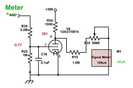
As you can see, the AGC meter will be changing in the range when the signal strength is most important.
Final Build and Results
The final, as built, schematic is below:
And here's what it looks like in my office under the OTL Amplifier:
(from left to right: tuning control, converter screen bias adjustment, AGC meter, volume, "-V2")
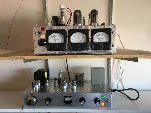
It took about 10 months (5/28/19 to 3/15/20) but now it's working. It's a little staticky and the tuning drifts as it warms but once I get the antenna sorted out, it should be very cool.