Wang 320 Calculator
This is the story of my adventures with a early 1970's vintage Wang 320SE calculator. It describes how I found it, figured out how it worked, developed tools to diagnose problems with it, and eventually repaired it. I will also describe how it works. I hope that people will find it interesting on its own as well as helpful to others working with similar calculators.
These pages have several sections:
The Quest
When I was in elementary school, I went to the Boston Museum of Science as often as my parents would take me. For a few years, there was a really cool Wang calculator there. It had a nixie tube display and an actual core memory made of little cores! There were four terminals and a central processing unit.
I always wanted to play with it but there was either a huge line of kids behind me waiting to pound the whatever out of the keyboards or it was broken because the kids had pounded the whatever out of the keyboards. Eventually, it disappeared.
Lately, I've been searching for a calculator like this to play with and they can be found on e-bay but they cost way too much, so I had to wait...

Then, a friend at UMass who knows I like old technology said he'd found "something with nixie tubes" that I might be interested in. He said it "was in the chemistry dungeon and there were more like it down there".
This was clearly part of something like the Wang calculator I'd been dreaming of since the 1970s. Finding one of these was like finding a fragment of the true cross - if there was one of these, there were likely more and maybe even the processing unit!
So I took a flashlight to the "Chemistry dungeon" that was being cleaned out (!) and found the other three terminals. But the processing unit was not to be seen.
Finally, in another room, I found it and now I had a complete Wang 320 SE calculator - vintage 1970! It consists of a 320SE "Electronics Package" serial number 283598 and four 320K keyboard/display units.

Since getting the calculator, I've found out some pretty amazing things about it. I learned a lot about it from Rick Bensene's excellent Wang 360 Site. It turns out that the 300-series do multiplication by taking the natural logarithm of the multiplier and multiplicand, adding them, and then taking the anti-log. This is described in two really cool patents: the patent for computing a logarithm with only an adder and the patent for the 300-series calculators. An advertisement for the Wang 300 series calculators can be found here. There is also an instruction manual.
This site helped inspire Bob Alexander to build a "Modern Electronic Package" for his Wang 320 terminal. It's a great bit of engineering. You can check out his site here. He even implemented a reverse-polish version... WOW.
Bringing it back to life Phase 1: De-Oxit and Re-capping
When I brought it home and fired it up, it did not work. The displays lit up and they responded to keystrokes but not in the proper way. Clearly, there was trouble with the keyboards and/or the electronics package.
Searching on the web led to this discussion. This site had two suggestions: First, to remove all the boards and spray liberally with DeOxIt. Tried that and it might have helped a little but not much. Second, one of the commenters in that thread said to measure the ripple on the power supply lines and "If there is more than 20 millivolts peak-to-peak ripple on any DC voltage, then there is probably a bad filter capacitor. So I measured the ripple on the -11V supply line and it was ~400mV P-P which is much larger than 20mV.
The +11V line looked similar.
So I replaced all the filter caps with new ones from Mouser (part # 661-ELBK350E602AMN3S) and re-measured. The ripple was exactly the same! So the caps were probably fine. (Sometimes I think that the obsession some folks with re-capping is just that, an obsession...)

SPOILER ALERT: as you'll see later, I was able to get the calculator completely working even with this level of ripple. So, if you find this in your 320, it's probably AOK.
Bringing it back to life Phase 2: Reverse-engineering the Logic Levels
So, now I was going to have to get serious. I was going to have to warm up my soldering iron and get out the logic analyzer. This was going to be fun.
The first step was reverse-engineering. What are the logic levels? How does the calculator work? There was very little information on the web but I did find patents and schematics.
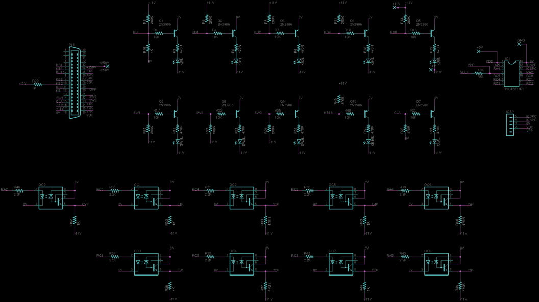
Since I was going to have to listen to and talk to the logic in the calculator, I first needed to know the logic levels it used. Were they standard TTL - not likely since this was strictly transistor-based. So I looked at the schematic.

There were lots of little inverters like this. The output will switch from about 0V to -11V depending on the input.
So, which is "logic 1" and which is "logic 0"? It turns out that it's not easy to figure this out from just a schematic.
So I had to get clever and try to find a place where some notes would give a hint.
On one of the pages, I found a circuit that should output a logic 1 when the T-counter (whatever that was) was 0 - or all 4 bits were logic 0. The output of this should only be logic 1 if all the inputs are logic 0.

There are two possibilities:
-
Hypothesis 1: 0V = "1" and -11V = "0"
-
If all inputs are 0 (-11V) then the output of the diodes will be -11V
-
Thus, the base of Q1 will be in the middle of a voltage divider: (+11V)-47K-{base}-6.8K-(-11V)
-
this puts the base of Q1 at -8V which will turn on Q1
-
this will make the output be 0V or a logic 1 - this matches the expectation
-
-
If any of the inputs becomes a logic 1, the output should go to logic 0.
-
Here, if any input goes to 0V (logic 1), the output of the diodes will still be pulled to -11V (since that's lower than 0V).
-
Thus, the base of Q1 will remain at -8V and the output will be 0V or "logic 1"
-
this is not right - the output should be a logic 0. So this can't be right.
-
-
-
Hypothesis 2: 0V = "0" and -11V = "1"
-
If all inputs are 0 (0V), then the output of the diodes will be 0V
-
Thus, the base of Q1 will be in the middle of a voltage divider (+11V)-47K-{base}-6.8K-(0V)
-
this puts the base of Q1 at +0.12V, which will turn Q1 off
-
this will make the output be -11V which is the expected logic 1
-
-
if any of the inputs become logic 1 (-11V), then the output of the diodes will be -11V
-
here, the base of Q1 will go to -8V and Q1 will turn on
-
this will make the output be 0V (logic 0) - this is what it should do.
-
-
Based on this, the most reasonable hypothesis is that:
-
-11V => logic 1
-
0V => logic 0
The best test of this hypothesis will be to actually use these values to test the keyboard/display units.