Transistor Binary Clock
I started with a gadget and an idea.
The gadget was a large (~ 12 x 12 inch) breadboard I'd picked up sometime when I was a kid. It had traces for 112 14-pin DIP sockets, each pin with two wiring holes. It also had really big fat bus bars for power supplies. I had two of these and I wanted to build something cool with blinking lights that I could hang on the wall.

The idea was based on a binary digital clock I'd seen at a friend's house. I wanted individual LEDs for each bit for hours (1-12 => 4 bits), minutes (0-59 => 6 bits), and seconds (0-59 => 6-bits). I also wanted to do it with discrete transistors, or as close as I could get to discrete transistors; that is, no logic chips.
For each bit, I needed a single T-flip-flop - one that could be set or reset and had a "toggle" input that would make it change state with a pulse. It also had to drive a nice bright LED. For that, I'd need a lot of transistors. Fortunately, I had a big stash of CA3045 5-NPN-transistor arrays.

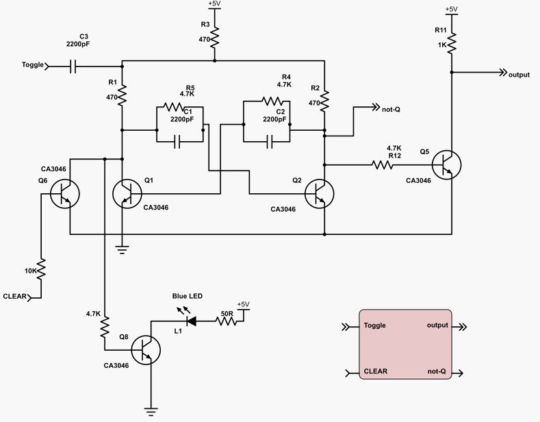
I searched around for a suitable circuit and found a great book of useful circuits: Electronic Counting Circuits by J.B. Dance. This particular circuit, called "An economical binary circuit" looked most promising, if I reversed the power supply polarity to accommodate my NPN (instead of PNP) transistors.

After much experimentation with resistor and capacitor values, I settled on this circuit for each flip-flop. I'll use the box abbreviation in later schematics.
I then needed to chain them together and configure them to reset properly. This is because the seconds and minutes counters can count to 63 but I need them to reset from 59 to 0 and the hours counter needs to reset from 11 to 1.
First the seconds and minutes:
(Note that, although the figure says "1Hz" for the master clock, it's really 2Hz since the 1's seconds display is the output of a flip flop, so its blink rate is 1/2 the input frequency. I couldn't find the original files to fix them; sorry.)

The diodes and transistors reset the counter the instant it hits 60 (binary 111100). If any of the not-Q's are 1, then the transistor is on and the counters are not cleared. When all the not-Q's are 0, (when the corresponding bits are 1), the transistor is off and the counters are cleared. So, it counts from 0 to 59 and the next count sets it to 60 for an instant, triggering the clear and immediately the clear goes back to 0.
I also added a center-off SPDT switch to select between a 1Hz source (to set the clock), no connection (to pause the clock while waiting for other parts to catch up), and the clear line from the previous row (to run the clock).
Then the hours - this is tricky since you need to reset to 1, not 0 when the counter hits 13. The "1's hours" flip-flop has a "set" input instead of a "clear" - it's the same circuit just connected to Q2 in the flip-flop.

As built, it took two CA3045's for each flip-flop. Here's how they were wired on the breadboard:

And, as of January 2016, it works! This video shows it going from 11:13:44 to 11:14:02.
It keeps good time. I've only had to change it for daylight savings time and for one or two glitches.