PDP-8/I on an FPGA
The Quest
I have always wanted a computer with switches and blinking lights on the front panel. From my youth, a PDP-8 was the classic 'blinkenlight' computer. Sadly, the prices on Ebay are outrageous, so I will have to live without the real thing.

By Digital pdp8f.jpg: Simon Claessen from The Netherlandsderivative work: User:Clusternote - This file was derived from: Digital pdp8f.jpg, CC BY-SA 3.0, https://commons.wikimedia.org/w/index.php?curid=63802103
DIY PDP-8?
I'd been trying to teach myself Verilog by building things on an Altera/Intel DE1-SoC FPGA development board. As I was reading about digital design, I came across "The Art of Digital Design" by Franklin Prosser & David Winkel. In it, there are several chapters devoted to designing and implementing a PDP-8. These included detailed state machine diagrams as well as detailed descriptions of all the parts of the PDP-8 system. It looked like I could build my own!
I found this process a great way to learn about Verilog, processors, state machines, asynchronous communication, FPGAs, and historical computing. I hope that my notes may be useful for others who might want to take this project on themselves.
Sources:
Although Prosser was very detailed, I needed a range of other sources of information to make this happen. These included:
-
A PDP-8 implemented in Verilog. While I did not use his Verilog code, there are a ton of useful files here including several test programs (see later) and the user manuals for them. There is an older version here that has a slightly different set of auxiliary files.
-
A mac-compatible PDP-8/e simulator program. This also included a binary version of FOCAL-8 that was my ultimate goal.
-
simh - a simulation of many processors, including the PDP-8
-
A Verilog simulation - this was a much faster way to do development since compilation is essentially instantaneous (and Quartus takes about 20 minutes to compile).
-
Icarus Verilog - a simulator
-
gtkw - a viewer for the output files
-
-
Other books:
-
Verilog By Example by Blaine C. Readler - a good intro to Verilog
-
Embedded SoPC Design With NIOSII Processor and Verilog Examples by Pong P Chu
-
-
Websites
-
Verilog for Finite State Machines. Good simple examples.
-
alt.sys.pdp8. A very helpful user group.
-
HD6120 datasheet. This is a "PDP-8 on a chip" and had useful details about extended addressing and interrupts.
-
-
People
-
Martin Bishop of Emeritus Solutions - for his helpful PDP-8 and Verilog advice
-
Vince Slyngstad from the alt.sys.pdp8 user group for huge help with IO
-
Rob Doyle from the alt.sys.pdp8 user group for huge help with interrupt handling
-
The final product: a 25Mhz PDP-8/I that runs FOCAL-8!
The final system takes advantage of both the FPGA and HPS (Hard Processor System) on the DE1-SoC. This is shown below:
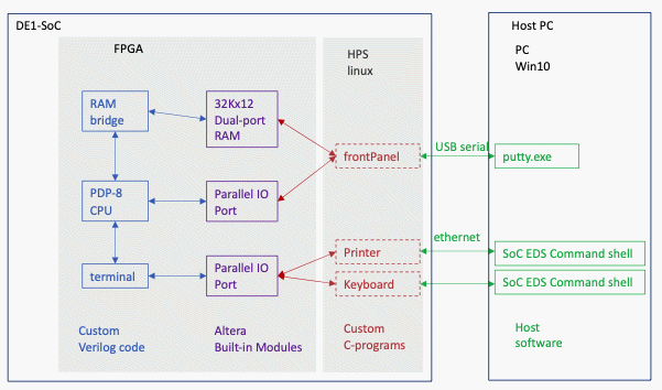
On the DE1-SoC, the PDP-8 cpu talks to the dual-port RAM and the terminal emulator which are built on the FPGA. These communicate with the Hard Processor System (HPS) in the SoC via some Altera megafunctions. These, in turn, are controlled by three C-programs running on the HPS. Finally, the host PC talks to these programs via the DE1-SoC's USB and ethernet interfaces. The three programs are:
frontPanel - this serves as the front panel of the PDP-8. It allows loading of files, setting the sr and the initial pc, resetting, and starting the PDP-8.
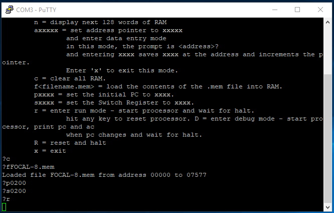
"c" clears the RAM; "fFOCAL-8.mem" loads the FOCAL-8 code; "p0200" sets the initial pc to 0200; "s0200" sets the sr to 0200; "r" starts the processor.
Keyboard this takes lines of text typed by the user and sends them to the PDP-8. It would have been more elegant to have keyboard and printer in one program but I couldn't figure out how to get ncurses working on the SoC...
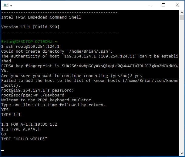
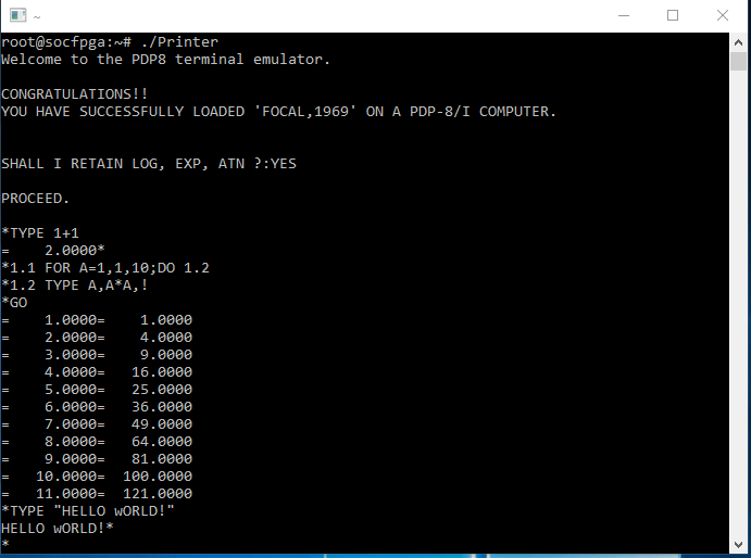
Printer displays the output from the PDP-8, both the echoed inputs and the PDP-8's responses. This shows a little bit of FOCAL programming as a final test. Success!!
Here it is running on the DE1-SoC.

The buttons, switches, LEDs, and display are:
* buttons:
* KEY0 = reset
* KEY1 = interrupt request
*
* switches:
* SW0 = high {25MhZ} (1) or low {1Hz} (0) clock speed
* SW1 = continue (1) or don't continue (0)
* SW2 = pc (1) or ac (0) on 4 HEX3-0
* SW3 = IF (1) or DF (0) on HEX4
*
* LEDS:
* LED0-4 = state
* LED5 = halted
* LED6 = interrupted
* LED7 = reset line from CPU
* LED9 = clock heartbeat
*
* HEX digits
* HEX3-0 = pc or ac
* HEX4 = IF or DF