PDP-8 on an FPGA IV: Timing Waveforms
These are from the Verilog simulation running on Icarus Verilog and viewed on gtkwave. They may be useful to others developing their own PDP-8's.
Generic Instruction cycle and memory read (TAD 0034)

The sequence is:
-
pc => ma (0160)
-
read instruction at 0160 (1034: TAD 0034) & increment pc
-
read [0034] into ac (4000)
Memory Write (DCA 0377)

The sequence is:
-
pc => ma (0203)
-
read instruction at 0203 (3377: DCA 0377) & increment pc
-
write ac (4400) to 0377 and clear ac
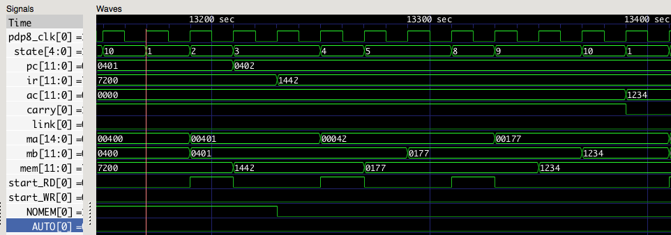
Indirect addressing (TAD I 0042)

The sequence is:
-
pc => ma (0401)
-
read instruction at 0401 (1442: TAD I 0442) & increment pc
-
read index value from 0042 (0177) into ma
-
read contents of 0177 (1234) into ac
Auto-indexing (AND I 0010)

The sequence is:
-
pc => ma (0611)
-
read instruction at 0611 (0410: AND I 0010) & increment pc
-
read value from 0010 (0000) and increment it
-
write 0001 back into 0010
-
read value from 0001 (5001) into the ac
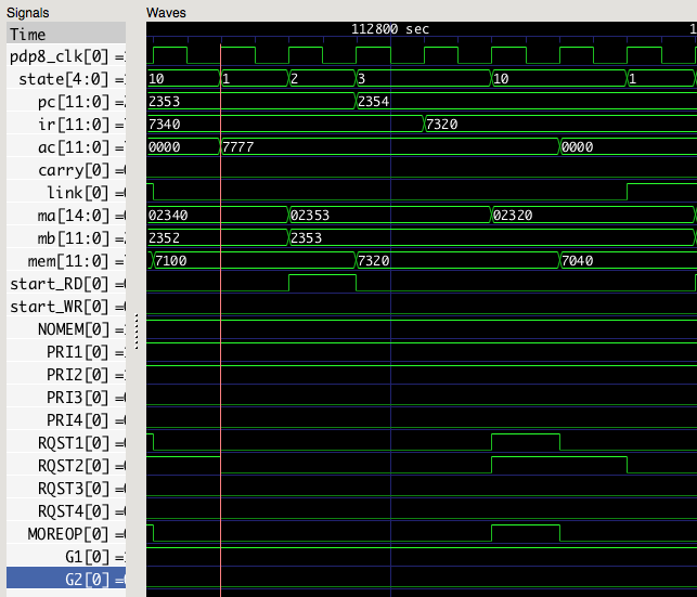
Microinstructions (CLA CLL CML)

The sequence is:
-
pc => ma (2353)
-
read instruction at 2353 (7320: CLA CLL CML) & increment pc
-
process the RQST1 items (CLA, CLL)
-
process the RQST2 items (CML)
-
ac = 7777; link = 1
Interrupt

The sequence is:
-
Interrupts are enabled with opcode 6001 (ION)
-
the next instruction, 7000 (NOP), finishes before interrupt occurs
-
interrupt does JSB 0000 (4000)
-
return address (2710) is written to location 0000
-
control transfers to 0001 which contains opcode 5402 (JMP I 0002)
-
it jumps to (0002) = location 2713
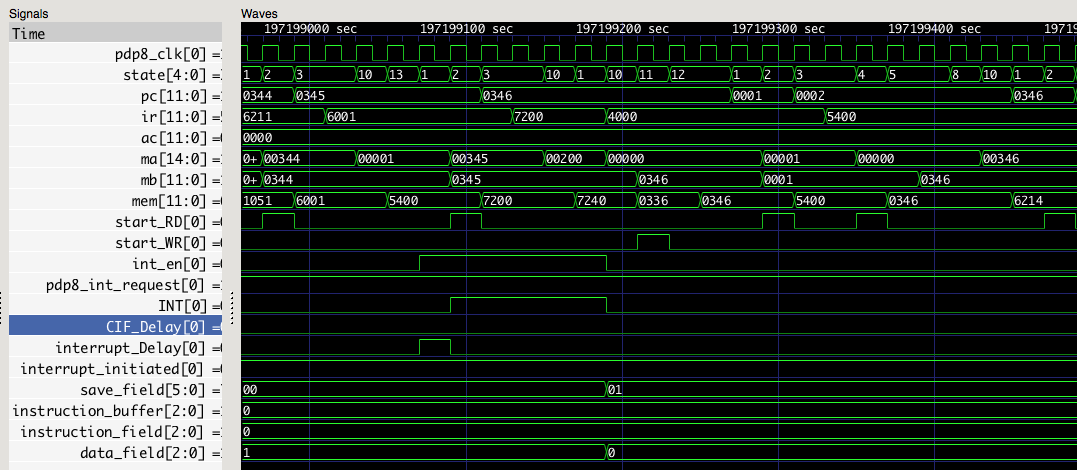
Interrupt with extended memory

The sequence is:
-
Interrupts are enabled with opcode 6001 (ION)
-
the next instruction, 7200 (CLA), finishes before interrupt occurs
-
interrupt does JSB 0000 (4000)
-
IF and DF are saved to SF
-
return address (0346) is written to location 0000
-
control transfers to 0001 which contains opcode 5400 (JMP I 0000) - the typical return from interrupt
-
it jumps to (0000) = location 0346