PDP-8 on an FPGA: State Machine Diagrams
These are modified from Prosser. The Verilog code is on a separate page that was prepared using the excellent Verilog to html converter v2html. The Verilog code has been edited from the version in the quartus project for clarity.
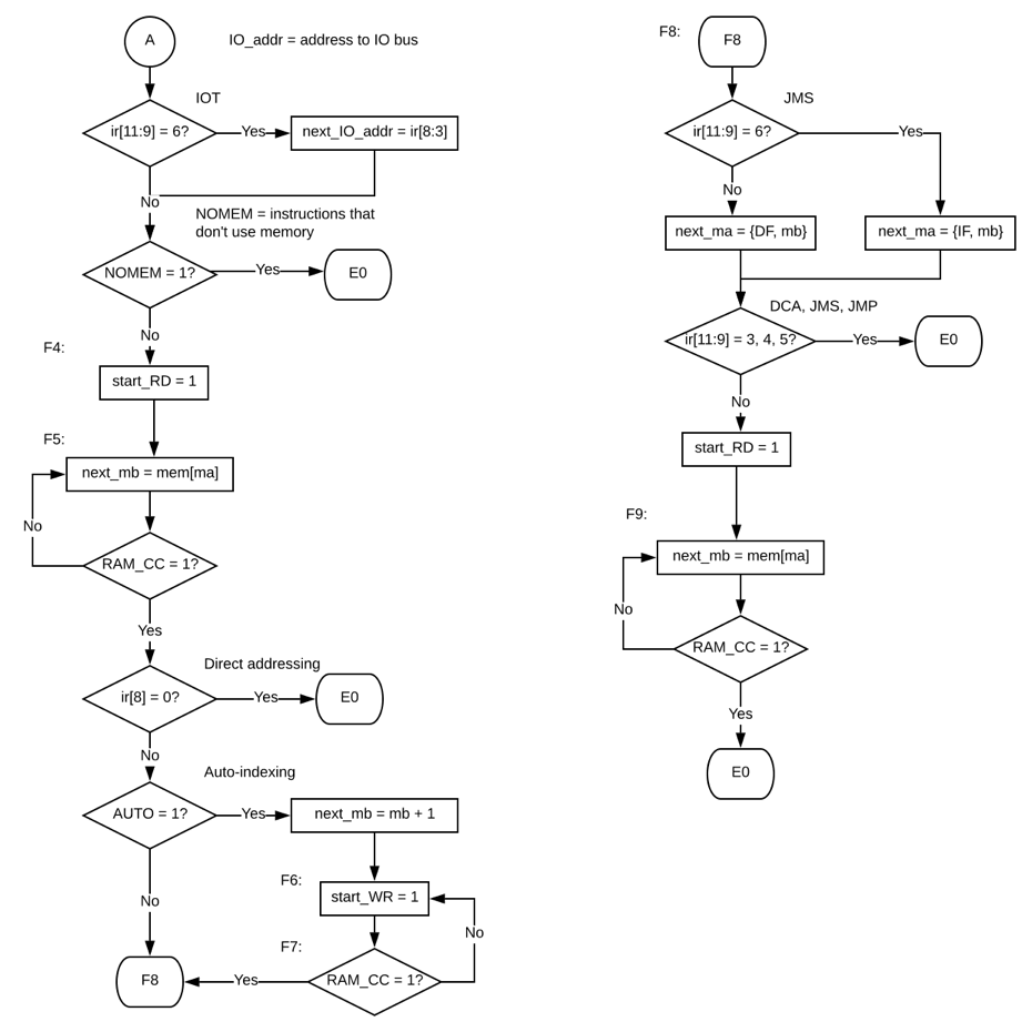
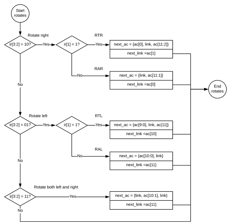
Note that, for all signals that need to stay stable for more than one state, I used a "next_X" format where X will change to the new value at the start of the next state. For example, in IDLE, next_halted is set to 0; this means that halted will become 0 at the start of F1.
First, the Fetch states - in Prosser, he does not split them into Fetch and Defer like the DEC-based PDP-8 descriptions do.

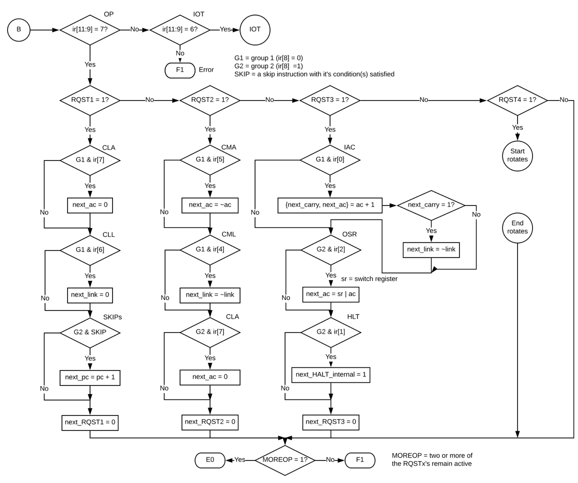
Next, the Execute states:

These are the Operate states - the Microinstructions.
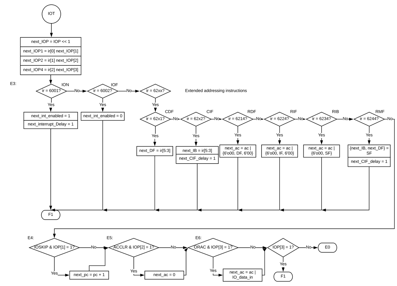
The extended addressing and IOP instructions:
