Wang 320 Calculator II - keyboard/display units
Bringing it back to life 3: Keyboard repair
Before I can test the Electronics Package, I have to be sure that the Keyboard/Display units were working fine. To do this, I need to build a test bench for them that does not depend on the Electronics Package. This test bench should test:
-
that all the keys generate the proper outputs
-
that proper inputs light the display properly
For this, I needed to see roughly what the signals on the keyboard lines look like. I used a Saleae Logic-Pro 16 logic analyzer - a truly excellent piece of test equipment if there ever was one - in the analog mode and got these traces from the keyboard lines as I pressed keys 1, 2, 3, 4, 5, 6, 7, 8, and 9 while the keyboard was plugged into the Electronics Package and powered up:

The KBKx lines are the binary code for the individual keys. KBC signals that a key was pressed and KBI is (probably) the response pulse to disable the key once it has been sensed. KBC and KBI seem to use the usual 0/-11 logic levels, but the KBKx lines seem to use +11V = "0" and 0V = "1" (the pulses go to about -8V and the bottom of the square waves is about 0V).
It looks like the -8V pulses on the KBKx lines are the "real signal" since the "0V plateau" lasts as long as you hold the key down and the system should respond on key down not key up.
The binary keycodes make sense:
-
Key 1 gives 10001 (17)
-
Key 2 gives 10010 (18)
-
Key 3 gives 10011 (19)
-
etc
Looking at the circuit, KBC is an input to the keyboard that enables the keys when KBC is logic 1 (-11V), so tie that to -11V through a 1K resistor (a common value for the collector load resistor in the 320).
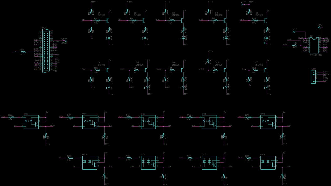
The next step is to create LED drivers for the various signals from the keyboard.
First, the KBKx lines that give the key codes. These switch from +11V (logic 0) to 0V and perhaps lower for logic 1. I tried using a comparator (LM319) but the input voltage swings exceed the maximum differential input voltage. So I settled on a simple transistor circuit.
The KBI line, which serves as an "any key pressed" line uses basically the same circuit but needs a 1K resistor pulling it down to 0V.

The three switches require a slightly different circuit. They switch between 0V and open-circuit through a diode and expect a pull-down resistor to -11V. Their LED circuit is this.

Bring it back to life 4: Display repair
That took care of the outputs from the keyboard/display unit. The next thing to look at was the inputs that drive the display. The display is multiplexed with
-
four digit-select lines called YK1, YK2, YK4, and YK8
-
these use the standard logic levels (-11V = "1" and 0V = "0")
-
the display has 10 digits
-
the sign digit is digit 15 (code 0 = "+"; code 9 = "-")
-
the MSD (leftmost digit) is digit 14
-
the LSD (rightmost digit) is digit 5
-
the decimal place location is digit 0
-
a decimal place location of 0 corresponds to the leftmost decimal position
-
-
-
-
four numeral select lines called EK1, EK2, EK4, and EK8 (also sometimes called T1, T2, T4, and T8)
-
these use the standard logic levels (-11V = "1" and 0V = "0")
-
code 0 lights numeral "0"; code 1 lights numeral "1"; etc.
-
any code higher than 9 results in a blank digit
-
code 15 is used by the calculator for blank digits
-
There is also an overflow light that, when signaled with a logic 1 blinks on its own.
I want to drive these with signals from a PIC 16F1823 microcontroller using a 5V supply. I devised some opto-isolator-based level shifters that worked. SPOILER ALERT: there's a better way - see later when I talk about testing the core driver boards. The input is to the left - one of the PIC I/O pins - and the output to the Keyboard at the right. I used 1K pull-down resistors for the E-lines and 470R for the Y-lines but I'm pretty sure either would have worked fine for both. I also included a pinout for the connector (top view looking into the female socket) since it's not obvious from the schematic.


Here's a movie of it in action:
From left to right, the LEDs are:
-
Clear All
-
Switch 1, 2, then 3
-
KBK16, 8, 4, 2, then 1 - these show the key code as a brief flash followed by weak steady light as long as the key is held down.
-
KBI - this is the "any key pressed" line - it flashes when any key is pressed.
The final detail is the timing - how fast is the display refreshed, etc. So I looked at the display control lines while the keyboard was attached to the running Electronics Package.

Here you can see the YK lines scanning the digits from right to left (remember that the logic is inverted: -11V = "1")
-
digit 0 (decimal point position) at position 8
-
digit 5 (rightmost digit) showing "8"
-
digit 6 (next digit left) showing 8
-
...
-
digit 15 (sign) showing +
I didn't note what the display was showing, but it should have been "+0000080000".
And the refresh rate is about 1kHz - it moves to the next digit every ~1msec.
So I wrote a little PIC code to exercise the display. It cycles through all the numerals and the corresponding decimal point locations, and with each round of numerals, it blanks a new digit. In action, it looks like this:
Using this, I fixed the 4 keyboard/display units. I had to replace some key switches with Microswitch 11SM1's that I got on e-bay. Also, a few of the nixie driver transistors were failed (shorted) - these were easy to find because certain numerals or the decimal point never turned off. The part number on the schematic and on the transistor (RCA 375 1006) was nowhere to be found on the web, so I did some poking around and settled on a ZTX458 ($0.61 each at Mouser). They worked fine.
I then connected them to the Electronics Package and it still didn't work properly.
That's a story for the next page.