RF Section
The purpose of the RF section is to provide a little amplification at VHF frequencies and to convert the VHF signal down to an IF of about 200kHz.
The original circuit used by Scroggie is rather complicated and involves some tricky frequency switching and AFC as well as using a harmonic of the oscillator frequency. Hunter's circuit is much simpler and uses a grounded-grid triode amplifier followed by a pentode oscillator/mixer:

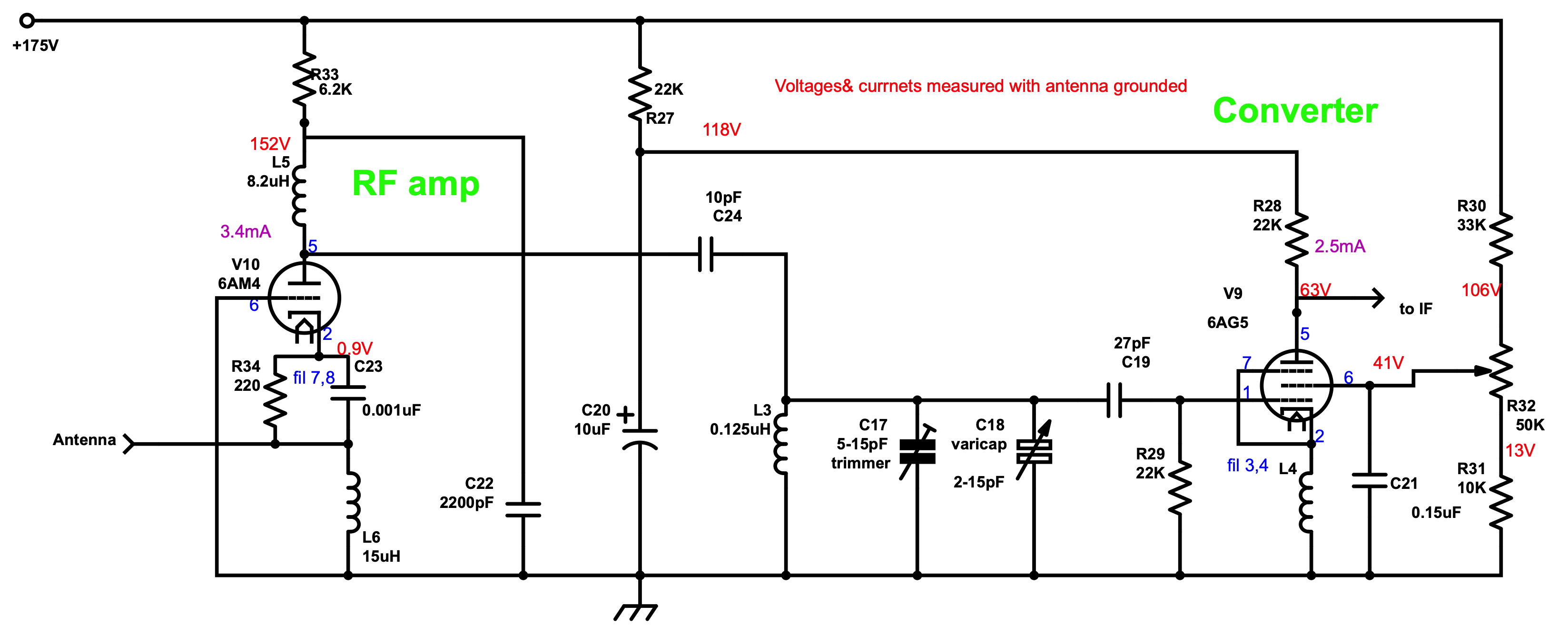
I did not have any 6BL8's but I had several 6AM4 UHF triodes designed for grounded-grid amplifier service as well as several VHF-rated pentodes. Hunter also mentions some trouble getting the pentode section of the 6BL8 to oscillate when at the high end of the FM band. He fixed this by adding some AGC. He suggests that separate tubes might fix this without requiring AGC.
After some experimentation, I ended up with the circuit below:

I had no trouble with oscillation, so I ended up using the AGC only for signal strength measurement.
Hunter mentions that the details of L4 are often critical for oscillation. I tried the choke he describes ("The chokes are made by winding 75cm of 25 gauge enameled copper wire on a plastic former of about 6.3mm diameter") but it would not oscillate reliably. So I ended up using a Millen 1.3-3mH choke in a little metal can which worked AOK.
I also tried several other VHF-rated pentodes with the same pinout (6AK5 and 6CF6) and found that the 6CF6 worked rather well but the 6AK5 would not oscillate reliably.
To be continued: