Demodulator
Here, the goal is to take the very distorted sine wave output from the three IF stages and turn it into pulses of fixed width. Scrodggie's design used a capacitor to differentiate the roughly square-wave output of a limiter into constant-width pulses. I wanted to try something a little different, partly because it would be a little cleaner and less AM-sensitive than Scroggie's and also because it thought it'd be fun to use some circuits I'd found in the RadLab books that Bill Kirby left to me.
In RadLab volume 19 "Waveforms" has a number of monostable multivibrator circuits. These are triggered on a rising or falling edge and generate an output pulse of fixed width governed by an R-C time constant. They shoujld be insensitive to AM and somewhat noise-immune as any trigger pulses that happen during the trigger cycle are ignored.
After extensive simulation in LTSpice and a lot of breadboarding, I finally got one that worked. It's on page 180 of RadLab 19. I used an E88CC tube because I have several and they're rated for 'multivibrator service':

It works like this:
-
At rest, V1 is OFF and V2 is ON. So the plate of V1 is near 250V.
-
A negative-going trigger pulse comes in.
-
It drops the cathode of V3 and V3 conducts.
-
Since V1 is off, it acts as an open-circuit and the pulse passes through C to the grid of V2.
-
This turns V2 off.
-
The plate of V2 rises fast and this is coupled through the 27pF cap to the grid of V1.
-
This turns V1 ON.
-
This is the triggered state: V1 ON and V2 OFF.
-
With V1 on, only a very large negative-going input pulse will be enough to get past V3 to disturb the charging going on with R and C. This prevents re-triggering during the triggered state.
-
C gradually charges thru R until V2's grid gets high enough to turn back on.
-
When V2 turns on, it's plate voltage drops.
-
This negative-going pulse is coupled through the 27pF cap and turns V1 off.
-
Now we're back to rest.
You can see this in the traces below using an E88CC dual triode, 200V on the HT and an Egg of -27V.
The trigger pulse is 20V tall and 200nS wide.

You can see that the negative-going edge of the pulse starts the cycle with V1 turning on.
With R5 = 10K and C3 = 100pF, the pulse is about 2.8uS wide; with C3 = 27pF, it's about 1uS (as above).
I could get them really short R5 = 1K & C3 = 27pF => ~350nS.
The shorter pulses have lower amplitude on V2's plate.
Noticed a problem, if the trigger frequency gets above ~100kHz, it starts dropping pulses. Perhaps the 'recovery time' to go back to the resting state after the pulse is over is too long. Changing C2 to 10pF lets it go to 340kHz if V2 is set just right.
Pulses don't need to be that short. Finally settled on C3 = 100pF; R5 = 1K; C2 = 10pF. These give:
-
Pulse width ~600nS
-
Stable triggering when V2 is between -25.5V and -21.8V
-
with V2 = -23.5V, the max reliable triggering frequency is ~270kHz
Tried playing with other part values:
-
R6:
-
if smaller, V2 goes down but the range of stable triggering shrinks
-
if larger, V2 goes up but it's hard to find a stable range of V2 for the full frequency range
-
Conclusion: stick with 89K
-
-
R7
-
tried 100K but the stable range of V2 was very small
-
Conclusion: stick with 200K
-
Also tried other triodes for the multivibrator:
-
driven by IF chain (2 stages + a 'limiter' wired like John Hunters but with a 6AH6)
-
measured
-
B1 = lowest stable V2 (if lower, it is astable; if higher, stable triggering)
-
B2 = highest stable V2 (if lower, stable triggering; if higher, not triggerable)
-
min Vin = with V2 set to average of B1 and B2 (middle of stable range), the minimum signal at 100kHz into the input of the IF chain that gives stable triggering)
-
Because the measurements are subject to some error, the sensitivities are about the same, so I chose the tube with the widest stable range of V2 - I'm assuming that a less 'finicky' circuit will be more reliable.
The notes in RadLab for this circuit say, "The major fault of this circuit is that every electrode is involved in the action; therefore, there is no free point that can be loaded with an output circuit without slowing the action."
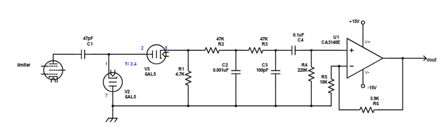
To deal with this, I buffered the signal at the plate of V2 with a cathode follower (high input impedance => little or no loading on the multivibrator) and followed that with the integrator and LPF from Hunter's circuit.:

When driven by the signal generator making a 120kHz sine wave carrier modulated to 75kHz deviation (±75kHz) with a 1kHz sine wave signal, a 2mV RMS signal into the IF chain resulted in 4.4V RMS 1kHz signal output - more than enough!
Comparing the Monostable-Based Detector to Hunter's Diode Detector
I wanted to see how this detector compared to Scroggie's so I built it following the limiter stage. It required an op-amp booster to have enough output to drive the QA400. These results should be taken with a small grain of salt as I carried out the measurements under conditions when the %THD and SNR were a little unstable.
I built the limiter and diode detector from Hunter's article and drove them with an FM signal (2mV RMS; 1kHz modulating signal) into the input to the IF chain.
The results are shown below:
The monostable is noisier (lower SNR) at low noise levels but quieter at high noise levels.
The monostable has lower distortion than the diode circuit.
The diode detector has higher distortion and a narrower range of carrier frequencies with low distortion.
Although the monostable was noisier, it was lower distortion and likely less touchy tuning since the range of low distortion carrier frequencies was larger. So, I went with the monostable multivibrator detector.
To be continued: