The IF Amplifier chain
I chose to start here for two reasons:
-
I had a clear specification from Scroggie's second article for the IF's frequency response (see below).
-
I could test the IF and detector with a known signal since I have a signal generator capable of generating a 150kHz carrier modulated with 75kHz deviation with a signal frequency of 1kHz.
-
I could not easily test the output of the RF section without a working IF and detector.
The target IF response from Scroggie's second article is:
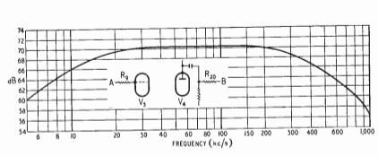
This corresponds to 70dB of gain (~3200-fold voltage gain) and the 50% voltage gain limits (-6dB) are 8kHz to 500kHz.
The first issue was which tubes to use. I wanted to use tubes that I had several extras of (in case of duds or burn-outs). Scroggie uses 2 EF80's (gm = 7400µmhos) while Hunter uses 6AU6's (4500µmhos). At least at the outset (see later), I didn't have enough of either. I did have several 6AH6's (9000µmhos) which sounded good, especially with their higher potential gain. I decided to use them.
I did extensive modeling in LTSpice which, while easier to play with than actual parts and good at identifying trends, was not fabulous at predicting the frequency response. In the end, I breadboarded it with QRPMe's "MeTubes" pads on a sheet of copper-clad board - shown below:

This made it easy to change parts and measure the results.
My full test rig was:
-
Heathkit IP-17 power supply
-
Siglent SDG 1032X signal generator
-
0-82dB variable attenuator (from eBay)
-
Tektronix TDS-210 oscilloscope
-
HP400FL RMS Voltmeter

I set the SDG-1032X to output 2V RMS sine wave at various frequencies and set the attenuator to drive the various IF stages with 2mV RMS.
I tried several gain stage configurations over several months of modeling, experiments and measurement.
-
I started with various pentodes in a 'standard gain stage configuration' and found that all of them showed significantly more high-frequency drop-off than the spec above
-
I tried a cascode since it has low input capacitance and I had some ECC88's and they're designed for cascode
-
None of these had the desired frequency response, so I even tried the EF80 circuit from the WW article. This didn't work like the graph either! I'm not sure how Scroggie measured his frequency response, but it didn't match my experience.
-
Finally, I settled on the "6AH6*" circuit with an inductor in the plate load to boost HF behavior.

The results are summarized below (note that each is a single stage while the graph above is for 2 stages:

Conclusions:
-
All show significant HF dropoff - even the EF80
-
Pentodes with higher gm have higher gain - as epxected
-
Adding a little inductance to the plate load helps flatten HF response.
Settled on the "6AH6*" circuit as the best. The IF would then consist of two of those stages followed by a limiter. Note that the final circuit differed from this - I ended up with another gain stage instead of the limiter. But that's a tale for later in the story...
I measured the gain to the input of V3 since the last stage distorts so much that RMS doesn't mean a lot. So, for the first two IF stages combined, the max gain is 5500 (75dB) at 200kHz and the 50% gain (-6dB) points are roughly 40kHz to 500kHz.
The output of the limiter when driven by a strong signal is below (plate voltage of V3):
As you can see, it is not a sine wave anymore, but it does have a nice sharp edges to trigger the monostable multivibrator in the demodulator.